還蠻少看到有人寫HP Switch 指令(大概就是看看User Guide吧),我把自己常使用的設定指令做一個紀錄,方便大家參考
1.建立admin使用者
2.建立vlan & 設定vlan ip
3.設定Web & Telnet登入
4.設定telnet ACL
5.設定Default Route
6.設定NTP
7.設定SNMP
8.設定VLAN 路由設定
9.設定802.1Q Trunk Port
10.設定VLAN 13 DHCP Server
11.設定VLAN 12 DHCP Relay
12.設定Static IP Source Guard
13.設定DHCP Snooping
14.設定Dynamic IP Source Guard
15.設定存檔 & 恢復預設值
16.設定Link Aggregation
17.設定IRF
1.建立admin使用者
<HP>system-view
[HP]local-user admin
建立管理者等級3 (最高權限)
[HP-luser-admin]authorization-attribute level 3
建立admin密碼 admin
[HP-luser-admin]password simple admin
設定web & telnet 服務
[HP-luser-admin]service-type telnet
[HP-luser-admin]service-type web
檢視設定
[HP]display local-user
2.建立vlan & 設定vlan ip
[HP]vlan 10
[HP-vlan10]port g1/0/20 to g1/0/24
設定vlan 10 ip address
[HP]interface vlan 10
[HP-Vlan-interface10] ip address 192.168.10.208 24
檢視vlan
[HP]display vlan 10
3.設定Web & Telnet登入
Web server 開啟設定
[HP]ip http enable
測試Web UI 登入
telnet server 開啟設定
[HP]telnet server enable
[HP]user-interface vty 0 4
設定閒置登出60分鐘
[HP-ui-vty0-4]idle-timeout 60
telnet 登入設定
[HP-ui-vty0-4]authentication-mode scheme
[HP-ui-vty0-4]protocol inbound telnet
檢視設定
[HP]display current-configuration
4.設定telnet ACL
建立ACL Number以及名稱
[HP]acl number 2000 name telnet
設定只允許192.168.10.0/24 網段可以登入設備
[HP-acl-basic-2000-telnet]rule permit source 192.168.10.0 0.0.0.255 logging
[HP-acl-basic-2000-telnet]rule deny source any
將規則套入vty
[HP]user-interface vty 0 4
[HP-ui-vty0-4]acl 2000 inbound
檢視telnet ACL
[HP]display acl name telnet
For Comware 7 telnet ACL
[HP]telnet server enable
[HP]telnet server acl 2000
5.設定Default Route
[HP]ip route-static 0.0.0.0 0.0.0.0 192.168.10.254
檢視路由表
[HP]display ip routing-table
6.設定NTP
[HP]ntp-service enable
[HP]clock timezone Taipei add 08:00:00
[HP]ntp-service unicast-server 118.163.81.61
[HP]display clock
7.設定SNMP
[HP]snmp-agent trap enable
[HP]snmp-agent target-host trap address udp-domain 192.168.10.209 udp-port 161 params securityname public
[HP]snmp-agent community read public
HP]snmp-agent community write public
[HP]snmp-agent sys-info location local
[HP]snmp-agent sys-info contact [email protected]
[HP]snmp-agent sys-info version v1 v2c
[HP]undo snmp-agent sys-info version v3
[HP]display current-configuration
8.設定VLAN 路由設定
切割vlan 12~14
[HP]vlan 12 to 14
指定port 1~4 vlan 12
[HP-vlan12]port g1/0/1 to g1/0/4
指定port 5~8 vlan 13
[HP]vlan 13
[HP-vlan13]port g1/0/5 to g1/0/8
指定port 9~12 vlan 14
[HP]vlan 14
[HP-vlan14]port g1/0/9 to g1/0/12
檢視設定
[HP]display interface g1/0/1 brief
設定 vlan 12 ip 192.168.12.254
[HP]interface Vlan-interface 12
[HP-Vlan-interface12]ip address 192.168.12.254 24
設定 vlan 13 ip 192.168.13.254
[HP]interface vlan 13
[HP-Vlan-interface13]ip address 192.168.13.254 24
設定 vlan 14 ip 192.168.14.254
[HP]interface vlan 14
[HP-Vlan-interface14]ip address 192.168.14.254 24
檢視Vlan設定
[HP]display interface Vlan-interface brief
9.設定802.1Q Trunk Port
設定Port 24為Trunk Port
[HP]interface g1/0/24
[HP-GigabitEthernet1/0/24]port link-type trunk
允許Trunk Port 通過所有vlan
[HP-GigabitEthernet1/0/24]port trunk permit vlan all
檢視設定
[HP]display current-configuration
10.設定VLAN 13 DHCP Server
設定DHCP Pool Name vlan13
[HP]dhcp server ip-pool vlan13 extended
設定DHCP 網段 13.100~13.200
[HP-dhcp-pool-vlan13]network ip range 192.168.13.100 192.168.13.200
設定DHCP MASK
[HP-dhcp-pool-vlan13]network mask 255.255.255.0
設定網域名稱
[HP-dhcp-pool-vlan13]domain-name vlan13.com
設定DNS Server
[HP-dhcp-pool-vlan13]dns-list 8.8.8.8
設定Gateway
[HP-dhcp-pool-vlan13]gateway-list 192.168.13.254
開啟DHCP
[HP]dhcp enable
綁定VLAN13 DHCP
[HP]interface vlan 13
[HP-Vlan-interface13]dhcp server apply ip-pool vlan13
11.設定VLAN 12 DHCP Relay
For Comware 5
開啟DHCP
[HP]dhcp enable
指定relay group 1 dhcp server 192.168.10.30
[HP]dhcp relay server-group 1 ip 192.168.10.30
開啟VLAN12 DHCP relay
[HP]interface vlan 12
[HP-Vlan-interface12]dhcp select relay
[HP-Vlan-interface12]dhcp relay server-select 1
檢視設定
[HP]display current-configuration
For Comware 7
開啟DHCP
[HP]dhcp enable
開啟VLAN12 DHCP relay
[HP]interface vlan 12
[HP-Vlan-interface12]dhcp select relay
[HP-Vlan-interface12]dhcp relay server-address 192.168.10.2
查看是否有DHCP封包
[HP]display dhcp relay statistics interface vlan 12
12.設定Static IP Source Guard
綁定Port 3 IP:192.168.12.181 & vlan 12
[HP]interface g1/0/3
[HP-GigabitEthernet1/0/3]user-bind ip-address 192.168.12.181 vlan 12
綁定Port 3 IP 192.168.12.181 & Mac Address:5cff-3509-68f7
[HP]interface g1/0/3
[HP-GigabitEthernet1/0/3]user-bind ip-address 192.168.12.181 mac-address 5cff-3509-68f7 vlan 12
13.設定DHCP Snooping
設定Port 24 為Trust Interface
[HP]interface g1/0/24
[HP-GigabitEthernet1/0/24]dhcp-snooping trust
檢視DHCP Trust Port
[HP]display dhcp-snooping trust
14.設定Dynamic IP Source Guard
指定Port 1 只能使用DHCP 取得IP
[HP]interface g1/0/1
[HP-GigabitEthernet1/0/1]ip check source ip-address mac-address
16.設定 Link Aggregation
[HP]interface Bridge-Aggregation 21
設定VLAN & LACP
[HP-Bridge-Aggregation21]port access vlan 10
[HP-Bridge-Aggregation21]link-aggregation mode dynamic
套用在Interface上
[HP]interface g1/0/48
[HP-GigabitEthernet1/0/48] port link-aggregation group 21
[HP]interface g2/0/48
[HP-GigabitEthernet2/0/48] port link-aggregation group 21
檢視LACP狀態
[HP]display link-aggregation verbose Bridge-Aggregation 21
17.設定IRF
兩台HP A5130 接線1接2 2接1 因為我的範例只有接一條線 ,所以1-1 接上2-2
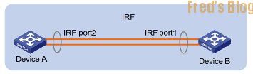
Device A 設定IRF Priority 10
[HPa] irf member 1 priority 10
Device B 設定IRF number 2
<HPb>system-view
[HPb]irf member 1 renumber 2
[HPb]save
[HPb]reboot
重開後 確認Device B interface 2/0/X
[HPb]display interface g2/0/2 brief
設定Device A 10G Port 關閉
[HPa]int ten 1/0/52
[HPa-Ten-GigabitEthernet1/0/52]shutdown
設定IRF Port 為ten 1/0/52
[HPa]irf -port 1/1
[HPa-irf-port1/1]port group interface Ten-GigabitEthernet 1/0/52
開啟 Device A 10G Port 並且Active IRF Por
[HPa] int ten 1/0/52
[HPa-Ten-GigabitEthernet1/0/52] undo shutdown
[HPa] irf-port-configuration active
Device B 10G Port 關閉
[HPb]int ten 2/0/52
[HPb-Ten-GigabitEthernet2/0/52]shutdown
設定IRF Port 為ten 2/0/52
[HPb]irf -port 2/2
[HPb-irf-port2/2]port group interface Ten-GigabitEthernet 2/0/52
開啟 Device B 10G Port 並且Active IRF Port
[HPb] int ten 2/0/52
[HPb-Ten-GigabitEthernet2/0/52] undo shutdown
[HPb] irf-port-configuration active
觀察IRF狀態
[HPa] display irf
[HPa] display irf link
Refer:
https://blog.imprezagt1031.idv.tw/download/hp-cisco.pdf
https://www.youtube.com/watch?v=gdY-9B9pCJw